
Centauri Carbon Chamber Heater Mod
In order to print high quality engineering materials, you need a consistent high temperature inside the chamber of your 3D printer. Unfortunately, the Centauri Carbon does not come with a chamber heater so I decided to create one and install it.
There are some pre-made chamber heaters out there now, most notably ones by Creality and Bambu, but one is poorly reviewed and the other is expensive. Also, the reason I bought a 3D printer in the first place is it gives you the ability to create something specced exactly the way you want it, so why wouldn't I just build my own?
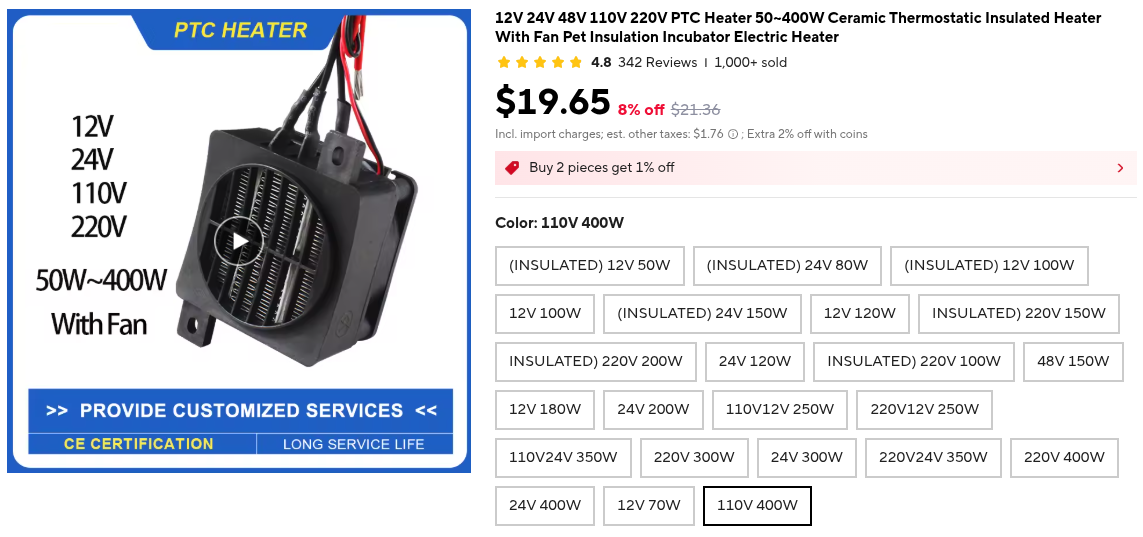
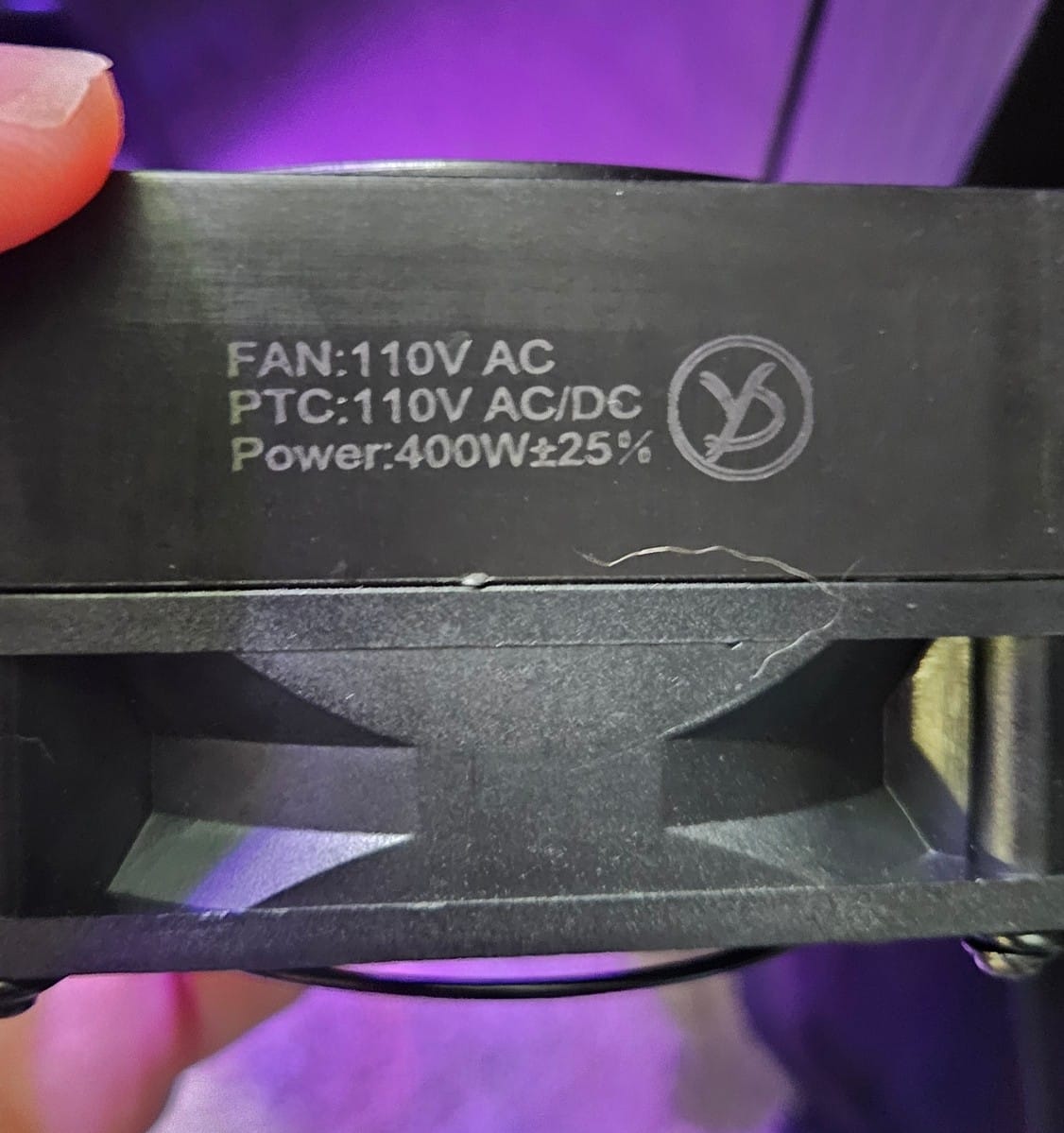
First I needed to acquire the parts. I needed some type of heater and something to sense the temperature in the chamber so that I know where I'm at. I settled on a PTC (Positive Temperature Coefficient) heater from a company in China called Yidu that only makes heaters. I specifically wanted both the fan and the heater to be 110V so that I didn't need a separate power adapter and could just run the whole thing off mains, and it needed to be powerful enough to get the chamber hot enough to print tough materials like polycarbonate reliably. 400W should be enough. It was $20 through AliExpress.
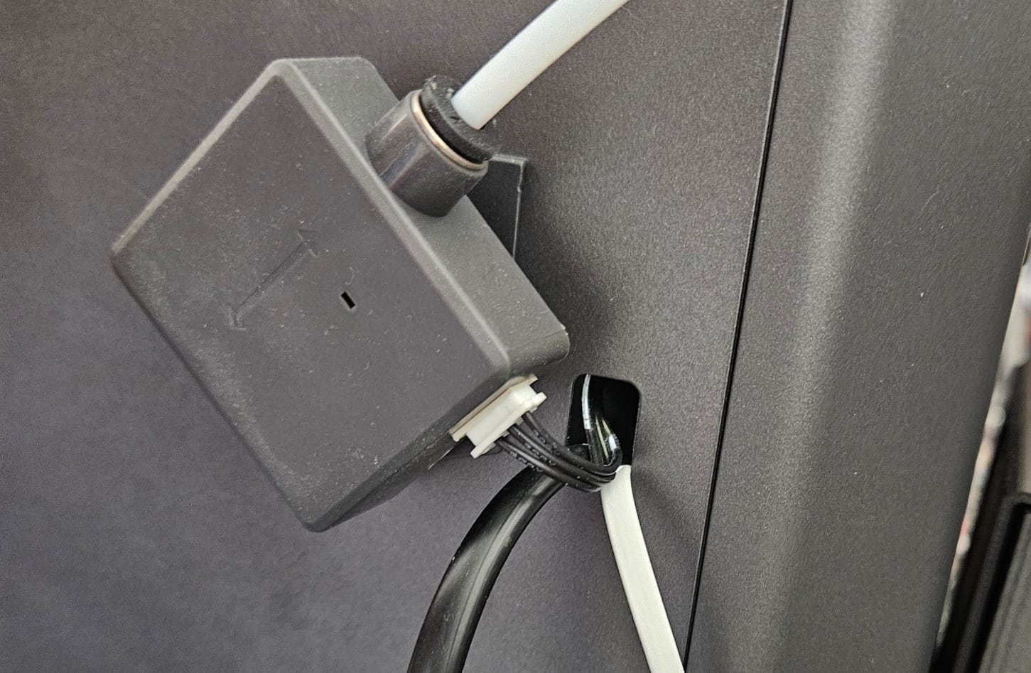
Since it's a constant power heater, I needed a way to turn it off and on depending on the temperature in the chamber. I settled on a thermostatic socket with a temperature probe and a bluetooth connection so that I could easily set temps via my phone. Mocreo I think is the brand? I'm sure it's just a rebranded OEM but it works.
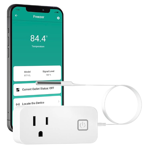
The heater is installed in the chamber and plugged into the socket. The temp probe is installed in the chamber as well and the socket is programmed to turn on and off when a certain temperature range is detected.
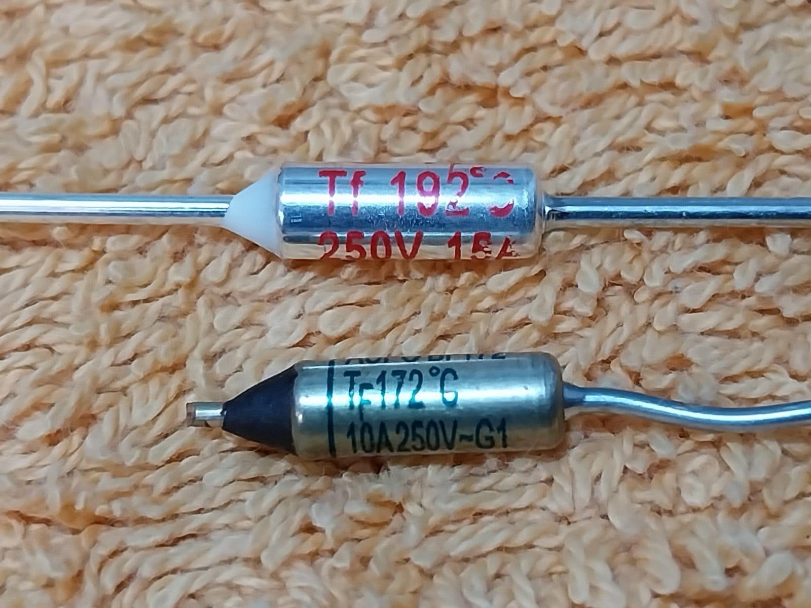
To protect against the socket malfunctioning and not turning off the heater, we need manual intervention. Thermal fuses are a good option to stop all power to the heater when a certain temperature is exceeded. I chose a thermal fuse that pops at 77C. This should be plenty hot enough to print whatever I want in the future. This is soldered inline with the heater and remains in the chamber. Special care should be taken when soldering thermal fuses so as not to trip them during the soldering process. I used a makeshift heatsink with an alligator clip between the fuse and the solder point.
As hot air rises, I wanted to mount the heater near the bottom of the chamber. It also needed to be in a spot that doesn't interfere with any of the mechanics. The back wall on the bottom left was a good location. The next step was designing a mount for the heater that can be used without drilling into the walls of the chamber.
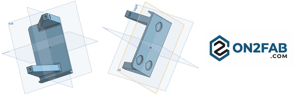
I like OnShape for design. It's a full-fledged parametric CAD program that runs from the browser so there is nothing to install, is free to use for non-commercial purposes, and doesn't restrict features or limit the number of projects you can have behind a paywall like Fusion360.

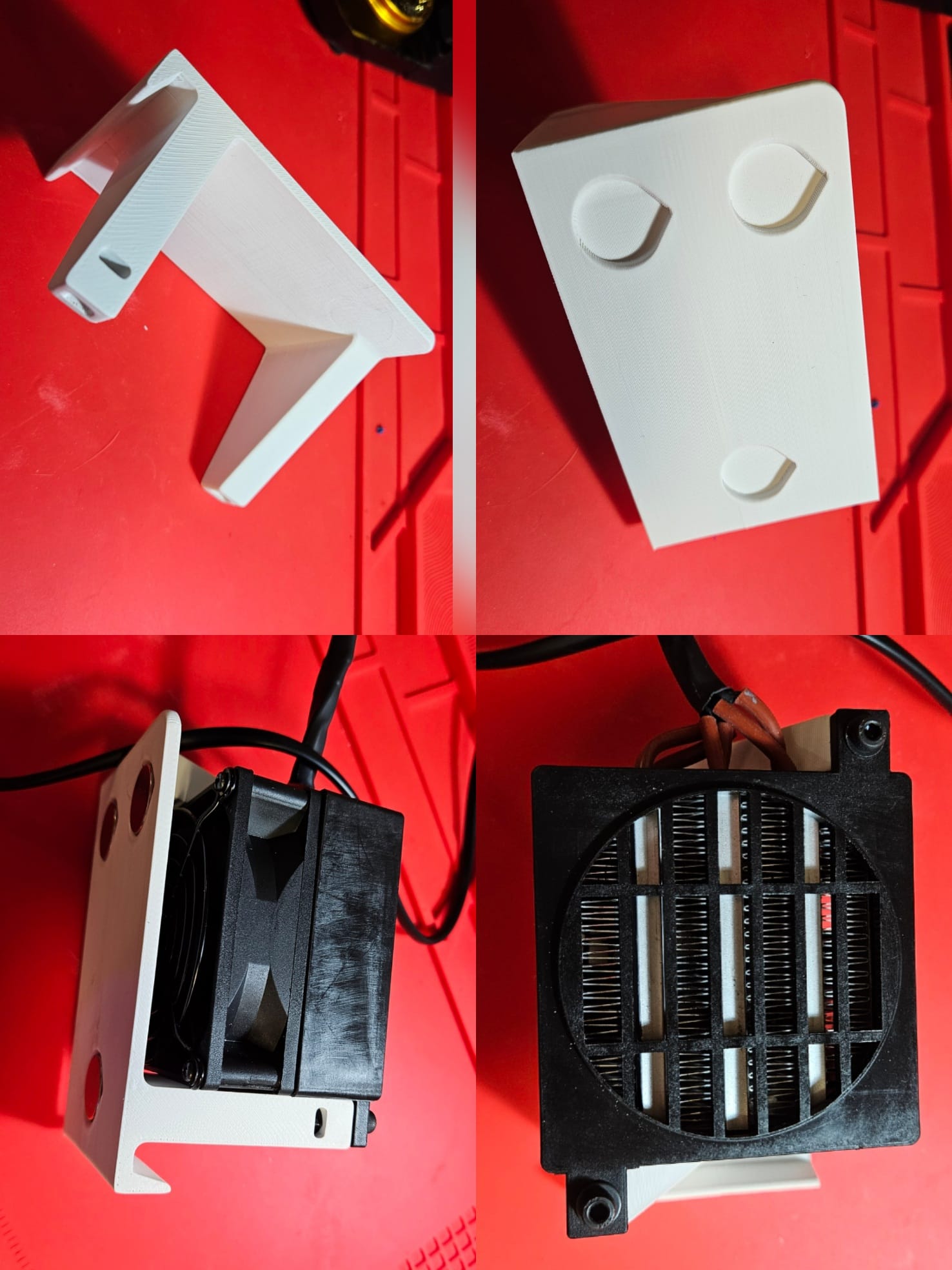
The floor of the chamber will be supporting the heater itself, so a small lip was added to the bottom. Also, if you can, design your parts to be as portable across platforms as possible. In this case that means no printed supports so it should be modeled in a way to make that possible. As the arms of the mount should be the strongest part of the printed piece, it will need to be printed so that they are parallel to the bed. An angled chamfer is added to each arm to make that possible without supports. If you print with them perpendicular to the bed, the arm strength is at the mercy of your layer adhesion instead of wall strength. Let's have a look at the back.
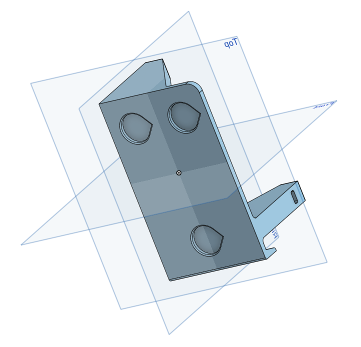
3mm by 19mm insets are added to the back which hold neodymium magnets. This will hold the back of the heater mount to the metal wall of the chamber. Note the teardrop shape of the insets. The mount will be printed on its side with the top of the teardrop facing up. This also eliminates the need for supports as the angle of the teardrop overhang is easily handled by the printer, whereas a perfect circle would give you a sagging top without supports. As the backside will be out of view, it doesn't matter what shape the insets are.
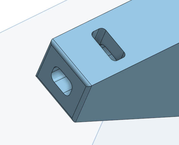
The last feature I want to point out is how the heater will actually attach to the mount. M4 bolts are passed through the frame of the heater into the mount arm and an M4 nut is slid through the side of the arm into a slot. Then the bolt is tightened.
After designing, we can start prototyping to check all the measurements. Use a cheap filament for quick prototypes, budget brand PLA or PETG. The final design is printed in high temp-resistant ASA.
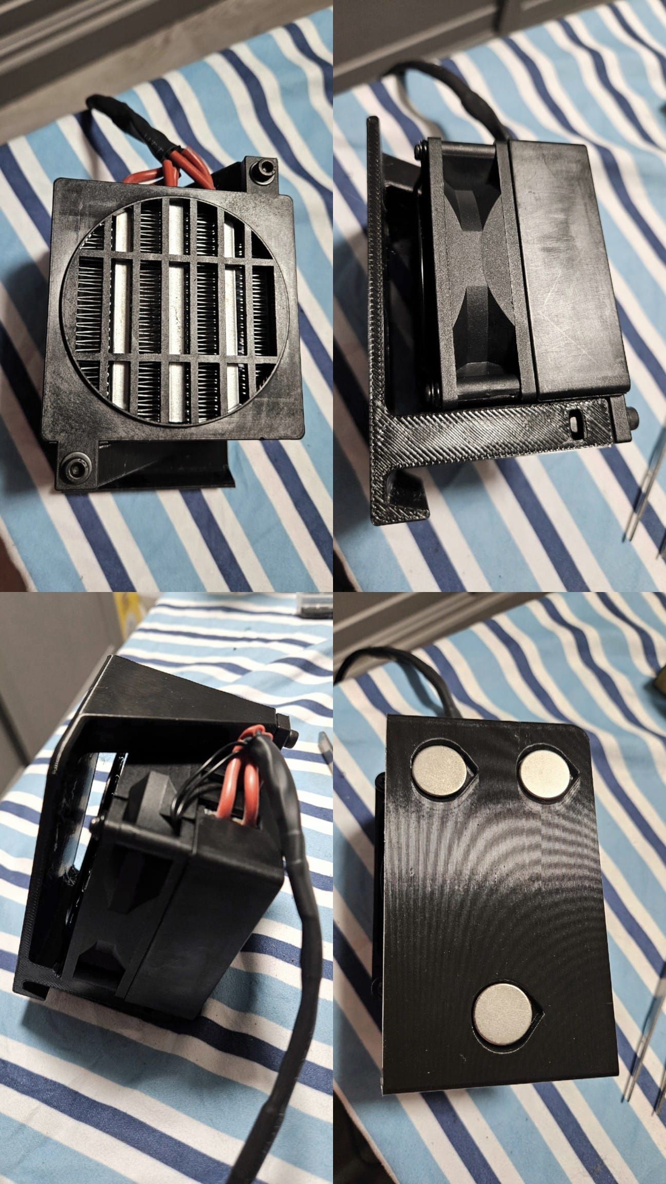
After about 3 iterations we have a functional model. The bolts and nuts fit together nicely and the magnets easily fit in the inserts. A 15mm gap is left in the back for the fan intake.This was printed from OrcaSlicer at extra draft settings. It's time to print the final version in ASA.
As I don't yet have a chamber heater, I have to close up all the vents on the chamber, turn on the chamber fan, and adjust the bed temp to 110C to create a makeshift convection oven. I also use painter's tape on the seams of the printer to keep hot air in. I let this run for about 20-25 minutes just to get the chamber temp up to 50C, where ASA performs best. As you can tell, this is time-consuming and very wasteful of energy, and doesn't guarantee a consistent temperature. When the chamber heater is installed, all of this will be unnecessary.
3D printing the ASA final heater mount
As you can see from the video, even after doing my best to raise the temp of the chamber, I still had a significant "shrink & shift" event during the print, leaving a prominent artifact along the edge. This is a very frustrating issue that solving is the entire point of this post.
Despite the poor printing performance, the mount still came out as functional and the heater was bolted on without issues and the magnets epoxy'd into the insets. As there are very few entryways into the chamber outside of the door and glass top, I needed a way to run the power and temp cables into the chamber without drilling or modifying the chamber exterior. The Centauri Carbon comes with a filament runout sensor and those cables are run through a pre-existing hole on the right hand side. This is the perfect spot to run the cables. The hole is too small for the power plug to enter but it's not really an issue as I have to cut the cord to solder in the inline thermal fuse anyway and I can reconnect it after mounting the heater.
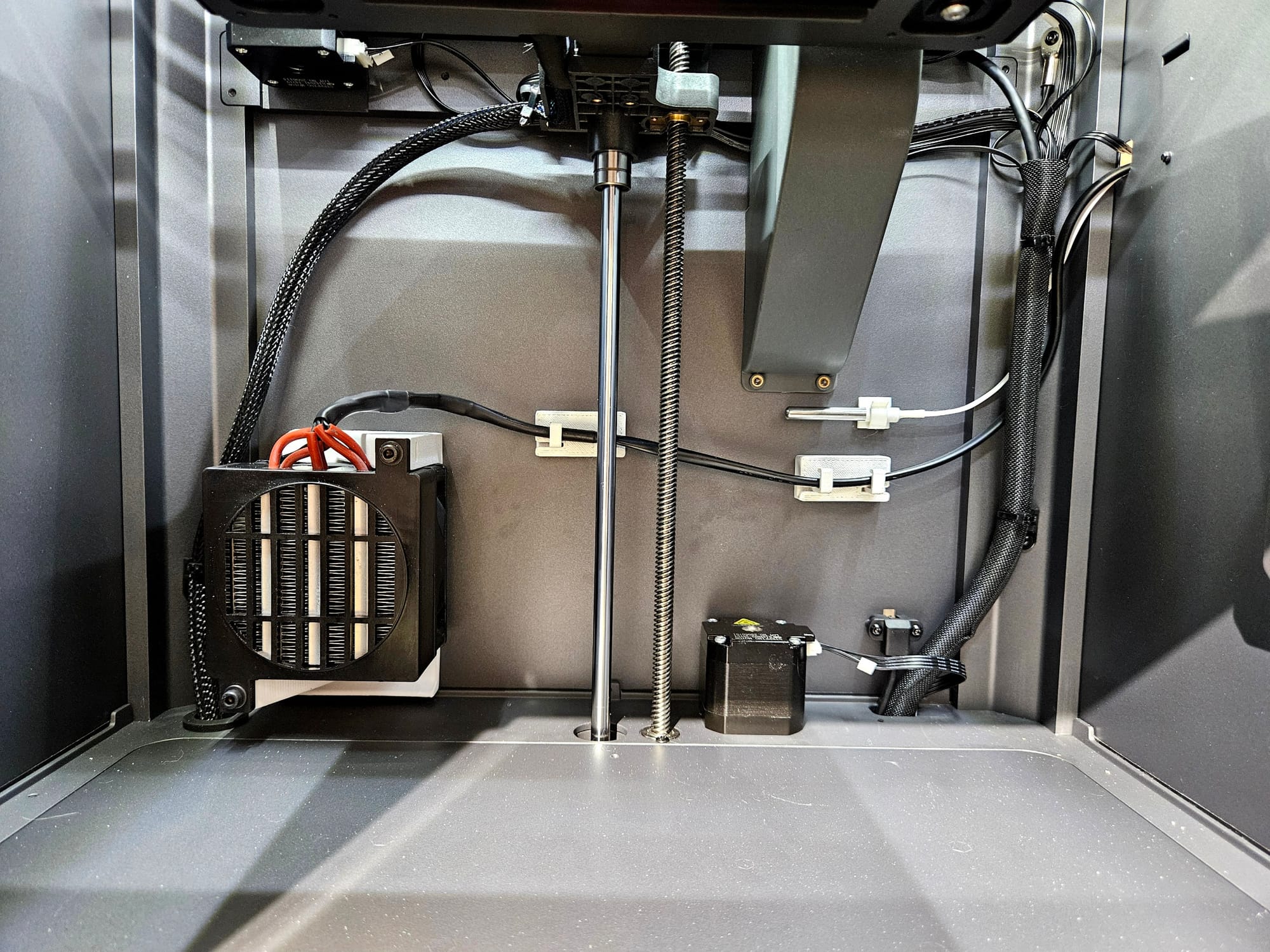
The mount fits in its spot nicely and the temp probe comes with its own mount. The mount for the probe has a glue back which won't last long in a chamber that can reach 70C so a neodymium magnet is used to secure it to the chamber wall. With the heater mounted some cable management is in order. The heater and probe cabling should not interfere with the carriage and other wiring within the chamber.
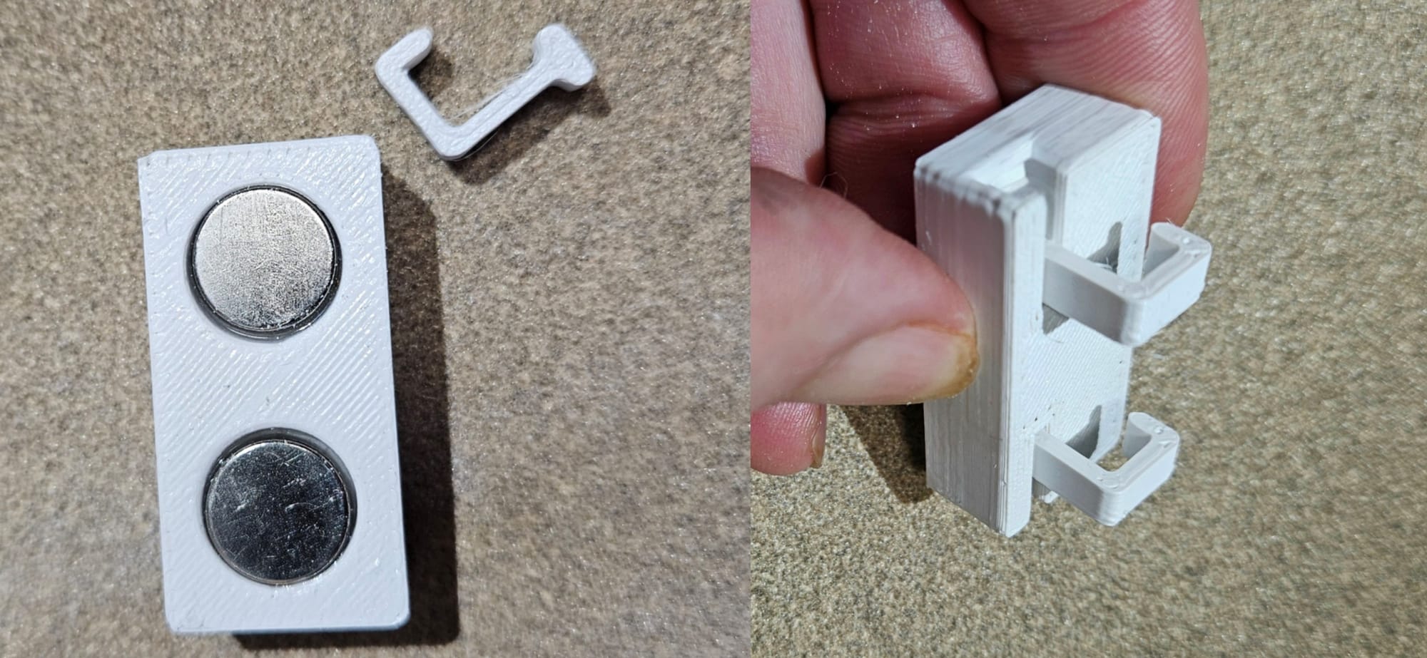
My first iteration of the cable holder was a failure because the strength of the supports was too weak due to the orientation that it was printed at. Printed on its back, the supports were at the mercy of the layer adhesion. The solution was to print them separate from the mount, so that they could be printed parallel to the bed and the walls would give the strength to the wire supports. Then they could be inserted into the mount through the side and would retain their strength. Neodymium magnets are epoxied into the back inserts and the cable mounts are placed on the back wall of the chamber.
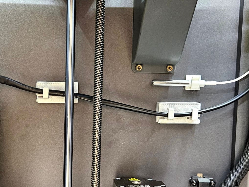
Once everything is mounted, the bed is lowered all the way and raised again and the mounts work, keeping the cables out of the way of the bed and carriage. The heater is in place and works as well. In the future I'll be testing ASA, nylon, PC, and more engineering materials and hopefully will no longer have the layer and warping issues I had before.
If you'd like to replicate my work, feel free to download the attached step files below.